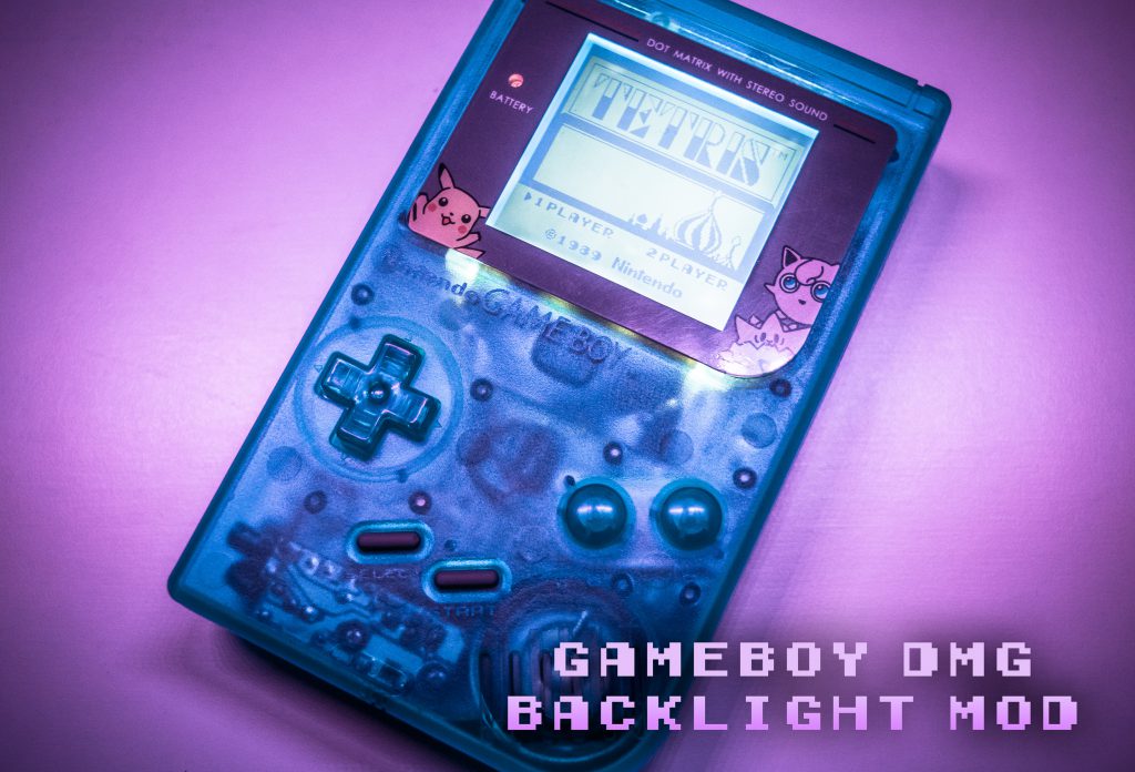
Playing Tetris on an original Gameboy in the early 90’s was as iconic as… Kurt Cobain on MTV? There was always one drawback to handheld gaming in the era of Mario, when the lights went out, so did your game. Unless of course you fitted your rig with the Gameboy’s “street lamp”.
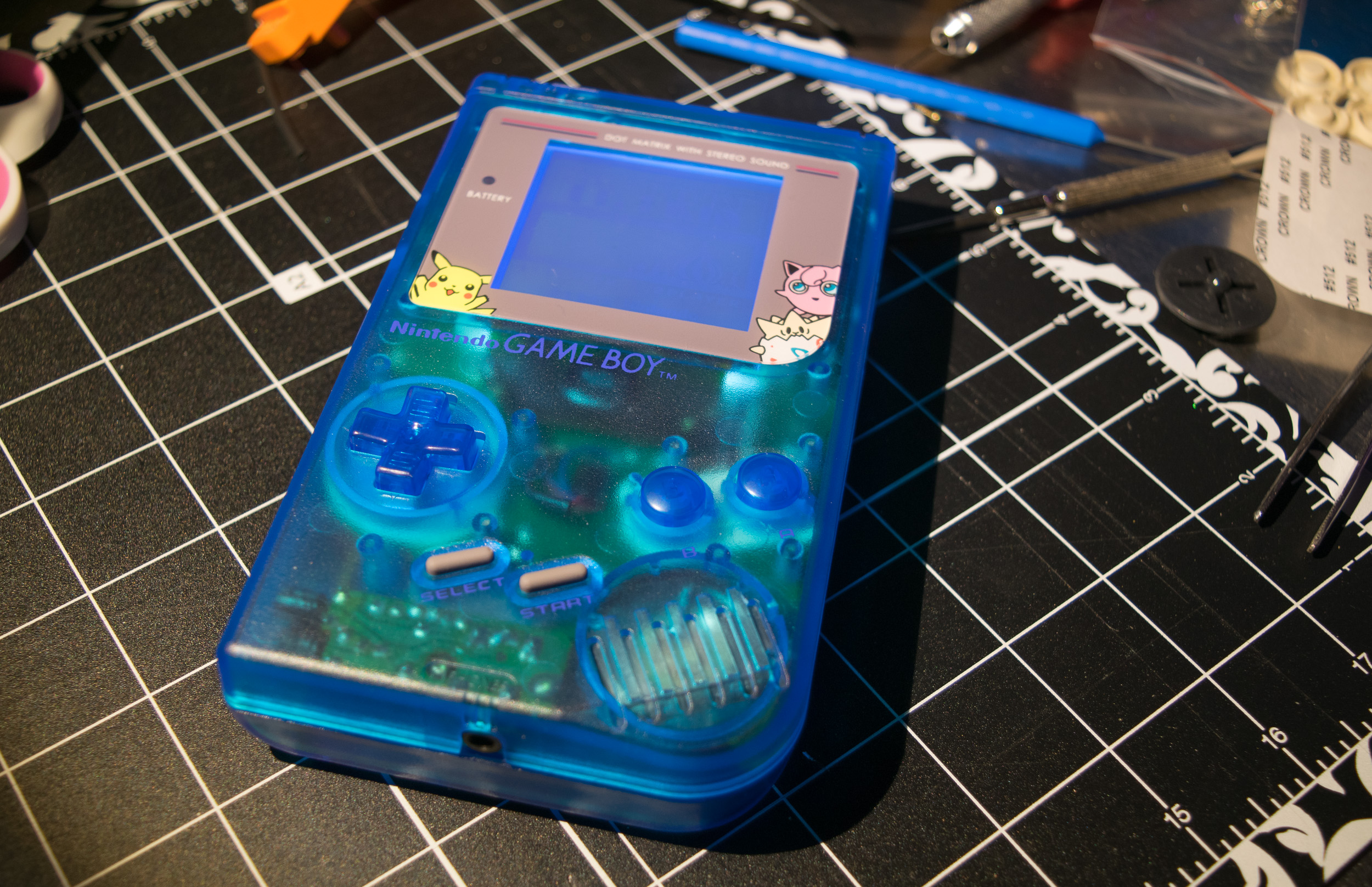
This past weekend, I embarked on the quest, for the second time (I’ll get why soon enough) to modify a Gameboy with a backlight and a bivert chip to improve the screens contrast. To glam up the unit, I also swapped out the case for a classy transparent blue one. All of which I picked up at handheldlegend.com, and by the way, their prices and shipping time were very agreeable.
There are many written and youtube tutorials available, guiding would be modders on the path of upgrading the Gameboy original; I feel any detailed guidance I could produce, would fall short in the area of experience. So instead, I would like to direct readers to the following resources that aided me in my retro modding experiment.
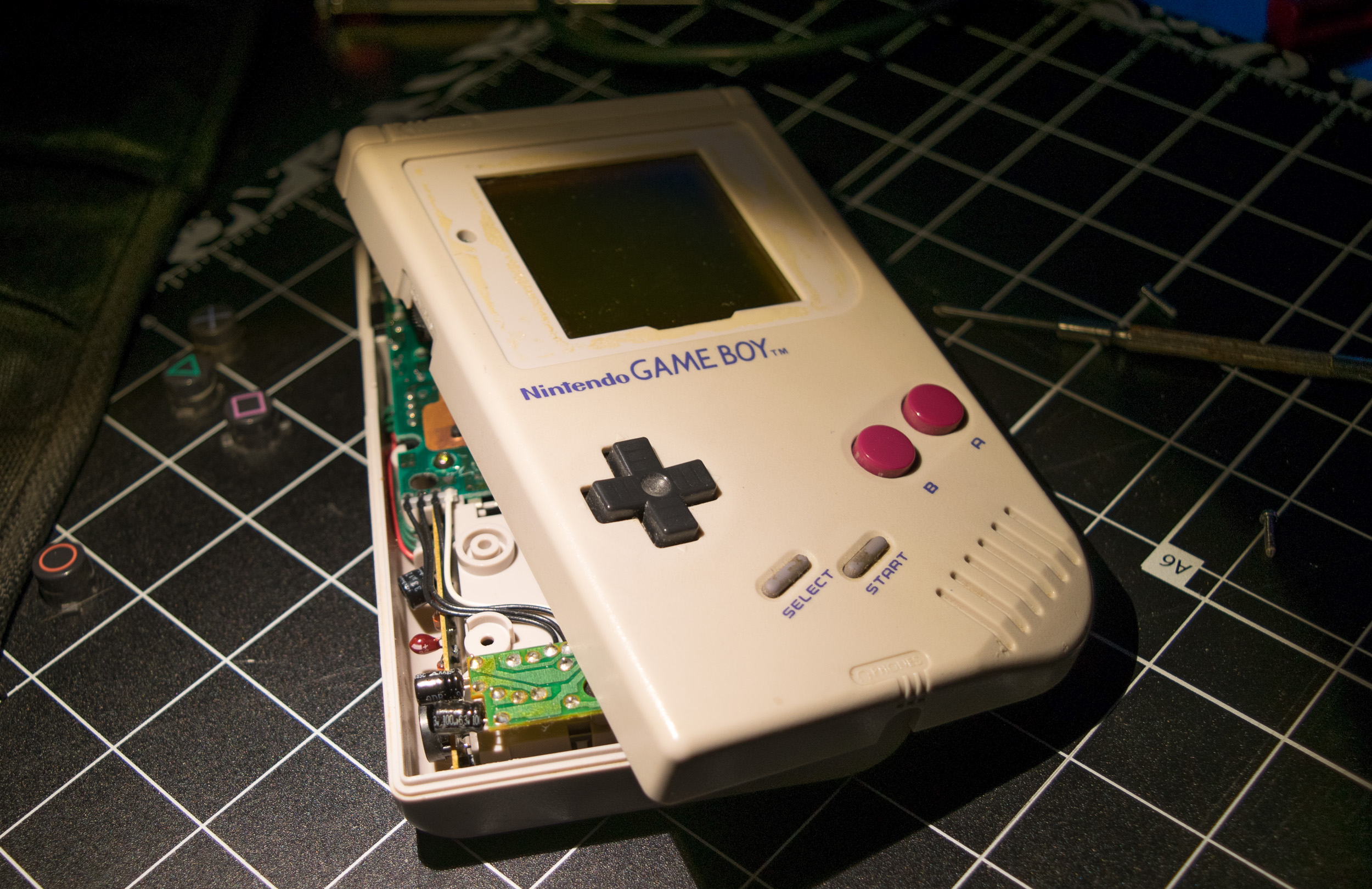
The case disassembly, the separation of the halves of the DMG is simple enough. The real fun begins when you start the process of peeling away the polarizing film from the LCD. In This Does Not Compute’s video, the author mentions the rare DMG model’s that have extra adhesive on the polarizing film. I was unfortunate enough on my first Gameboy to run into this problem. The two learning moments I had here are:
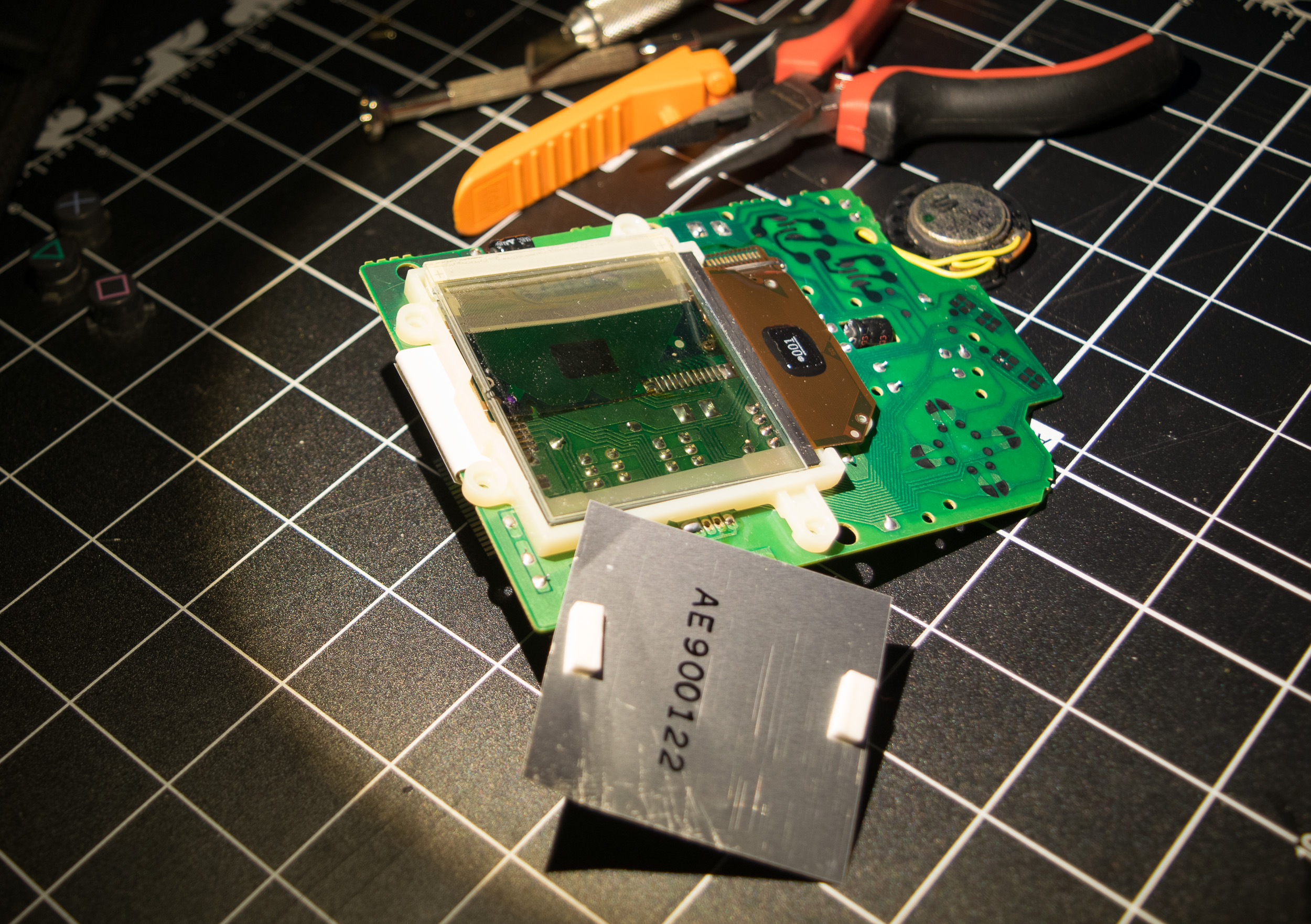
- It’s very true, you can’t tilt the LCD away from the PCB any more than about 45 degrees, the ribbon cable is insanely fragile and will be irreparably damaged if you exceed the ribbon cables limits.
- Despite what other modders say, models with extra adhesive are not cleanable without some heavy duty solvent. I tried scrapping the residue from the LCD with a combination of rubbing alcohol and a flat razor blade; the result was a scratched LCD, despite my diligent efforts of slowly and evenly scrapping.
Position the backlight into place and solder the Vin wire, with the supplied resistor and the ground wire to their respective nodes on the LCD. Next, you’ll need choose your grounding and power locations. Some tutorials I’ve read suggest taking power from a shared power rail, which is supplied by the batteries. But directly below the bottom ribbon cable for the LCD is the display’s capacitor. In my opinion, the capacitor would provide the cleanest Sine wave for the backlights Vin.
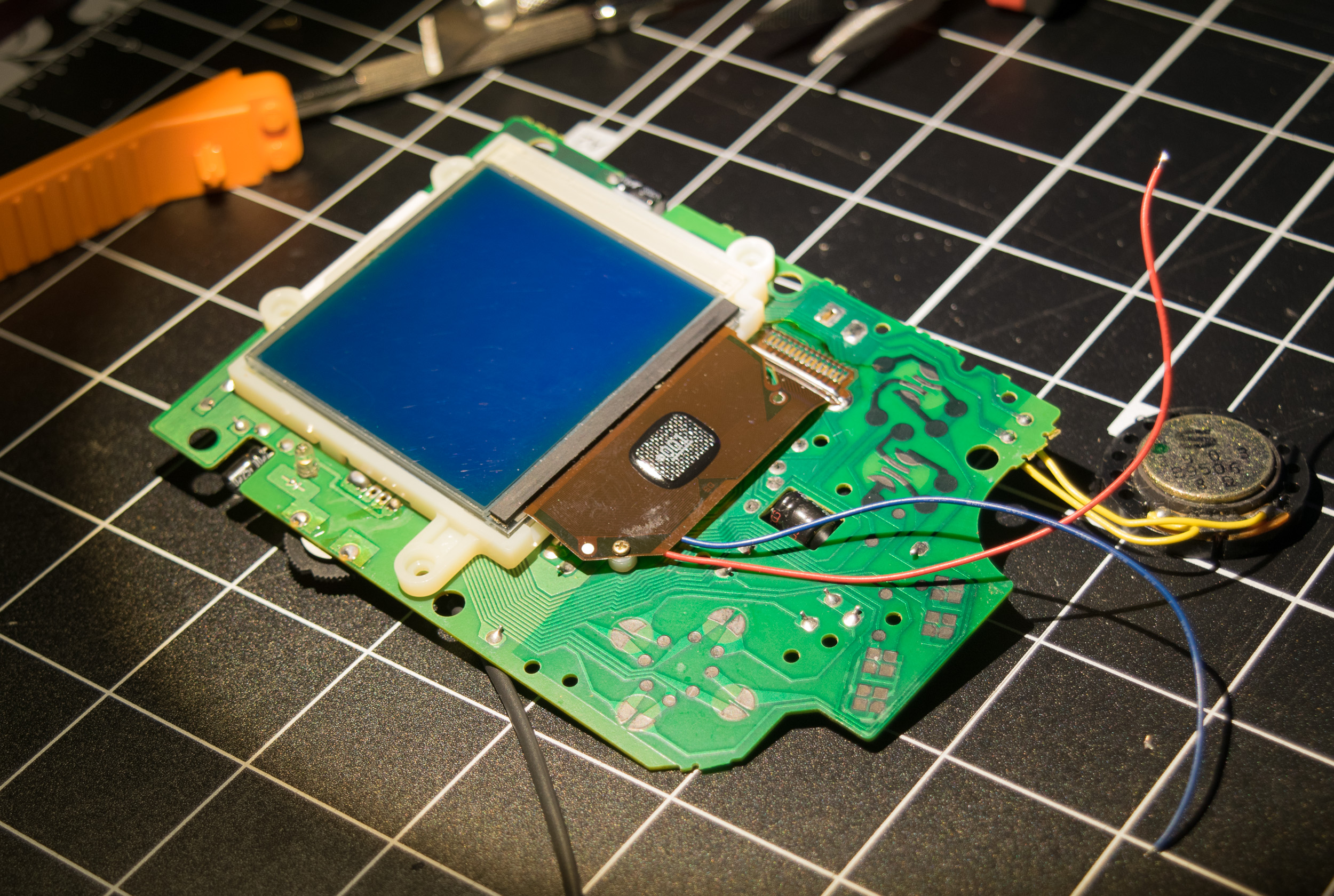
If you’re continuing your project by installing a bivert chip to improve the contrast of the display, now is probably a good point to test if the screen install has been successful.
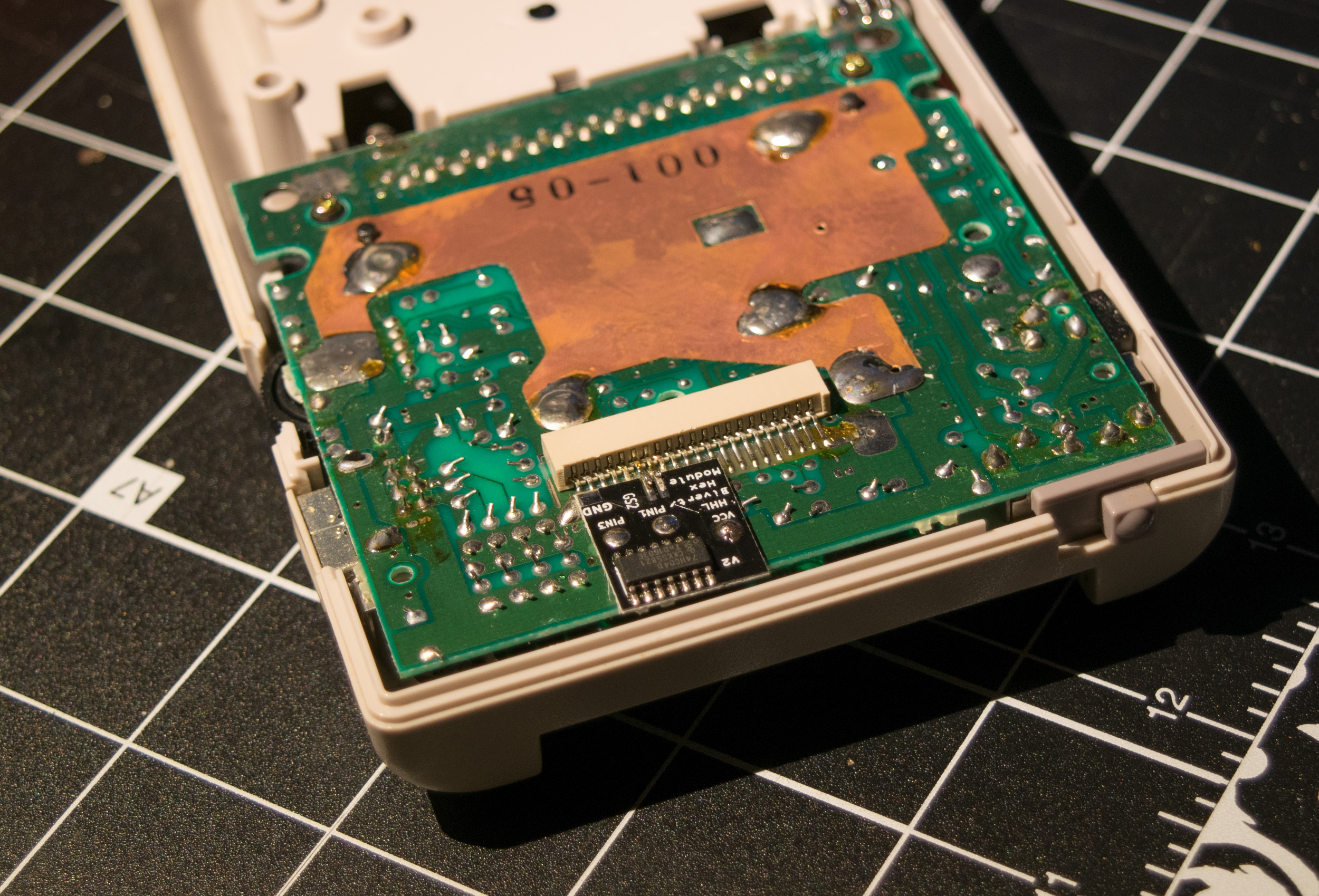
Installing the bivert calls upon your soldering powers yet again. In this case to desolder pins 6 & 7 (from the right) of the female connector that joins the halves of the Gameboy together, this can be achieved by using desoldering braid to soak up the pin’s anchors. The greatest chance for damage at this step is to either a). Leave the soldering iron on the pins for too long, or b). Break the fragile pins on the connector.
One issue I ran into, and it appears others had similar problems, was the connection between the bivert board and main PCB. Dropping a lump of solder here is not enough. It will appear the points are imbedded, but to ensure the connection is complete, heat the three solder drop points an additional half second each.
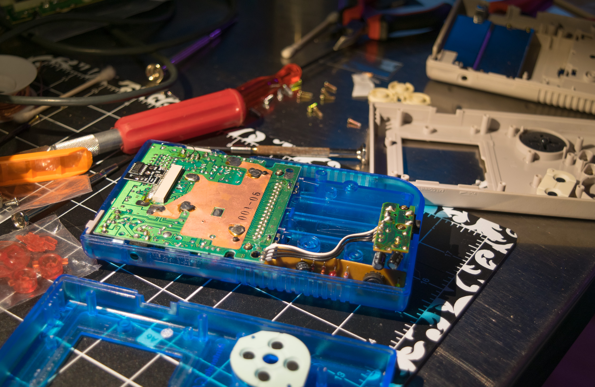
Lastly, to show off my work, I swapped the traditional grey case for a dazzling transparent blue replacement. From start to finish, the process took me around two and half hours. Admittedly, I did have some practice from the failed attempt.


Leave a Reply